30+ wifi transceiver block diagram
An SN65HVD72 transceiver provides the RS-485 interface with 12 kV. 1 RF transceiver EMLAB Block diagram of wireless.
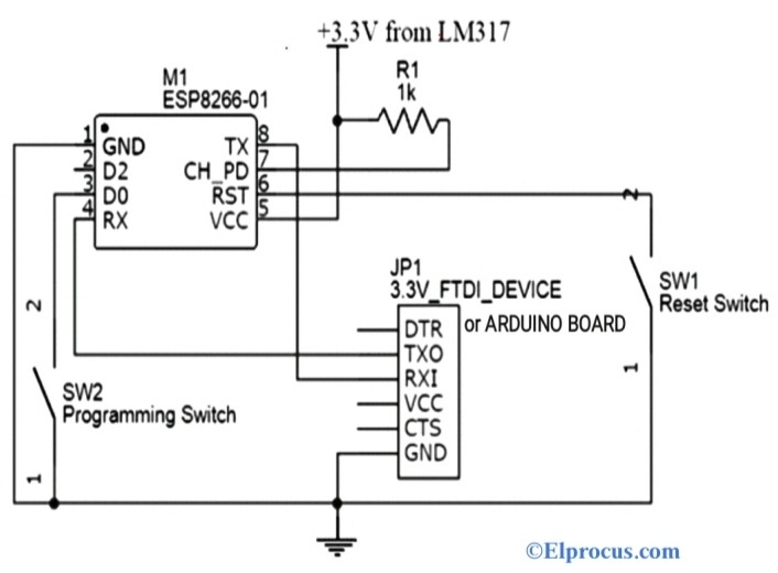
Esp8266 Wi Fi Module Datasheet Working Its Applications
300 MHz IEEE 80211b Modulation.
. Its free to sign up and bid on jobs. 345kB 43175 bits Date Submitted. So that the transmitted signal does not interfere with the.
Normally In transceivers the transmitter path is isolated from the receiver section. Simulink block diagram of the transceiver system is illustrated in Fig. For Bi-directional communication in a single path These are implemented by isolating one section from another which are connected in a single point.
Mod Demod SPDT Detector. A large amount of capital manpower and material resources are. 5 GHz UNII Unlicensed National Information Infrastructure TotalUNII Bandwidth.
Using Model-Based Design with Simulink and Stateflow provides a seamless design workflow. Network and a Wi-Fi network. Search for jobs related to Wifi transceiver block diagram or hire on the worlds largest freelancing marketplace with 20m jobs.
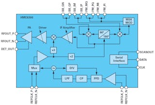
Basic Wireless Transceiver Block Diagram. Cell Phone Transceiver Block Diagram. Driver LNA LNA IF Amp VCO.
Wireless Fidelity Card Block Diagram details for FCC ID MSQWIFIG made by ASUSTeK Computer Inc. Note that the voltage swing of the instruction waveform is about -10 V. WIRELESS TRANSCEIVER BLOCK DIAGRAM.
VCO DAC DAC ADC. Adobe Acrobat PDF - pdf. The 16-Gbps input data generated from a random integer source is modulated in OOK and fed into a pulse shaping.
SPDT SMAF x2 From Two Antenna Channel Select SMAF. Mobile phones have exploded in recent years. IEEE 80211a WLAN Frequency.
TYPICAL TRANSCEIVER BLOCK DIAGRAM. Rs 232 waveforms 8 This is the instruction bytes. BPF PD DCA BPF IF BPF Mixer DCA.
The design of a wireless transceiver requires multiple engineering disciplines to make it work. Document Includes Block Diagram PowerPoint Presentation.
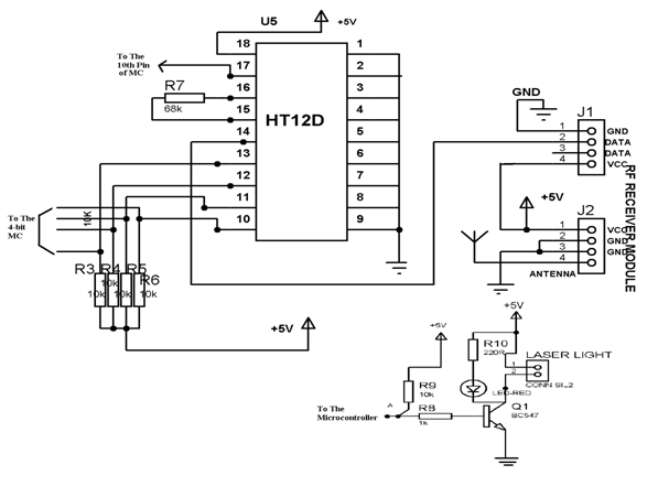
Wireless Rf Module Rf Transmitter And Receiver Latest Applications
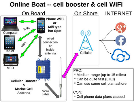
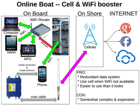
Onboard Wifi And Cell Booster Strategies The Diagrams Panbo
![]()
Overview Of Wireless Pc Communication System Using Transceiver
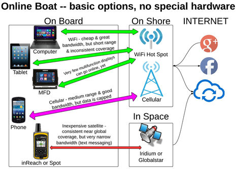
Onboard Wifi And Cell Booster Strategies The Diagrams Panbo
Onboard Wifi And Cell Booster Strategies The Diagrams Panbo

Mla 30 Plus 0 5 30mhz Ring Active Receive Antenna Sdr Loop Antenna Low Noise Medium Short Wave Radio Short Wave Antenna Integrated Circuits Aliexpress

In Building Distributed Antenna Systems Das Diagram Antenna Base Transceiver Station Fiber Optic
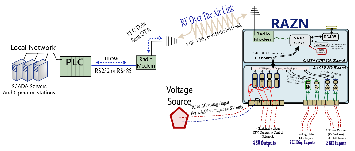
Remote Autonomous Zone Nodes Razn Raveon Technologies
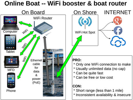
Onboard Wifi And Cell Booster Strategies The Diagrams Panbo
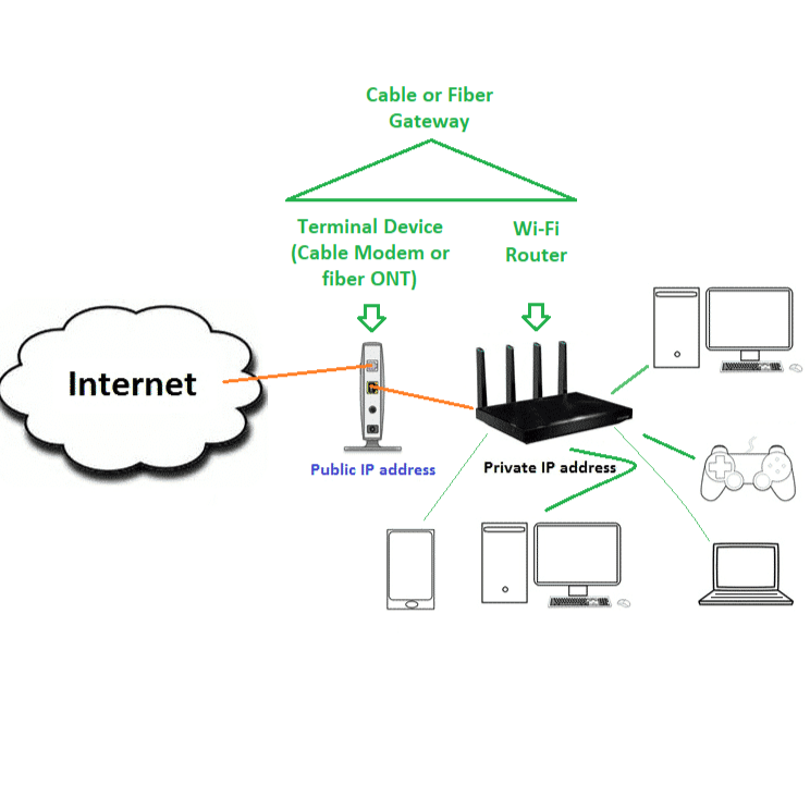
Home Wi Fi Network 101 Beginners Best Tips Dong Knows Tech
60 Ghz Wireless Data Interconnect Targets Slip Ring Applications Electronic Design
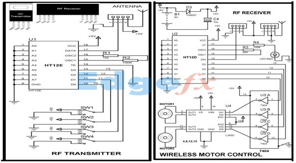
Wireless Rf Module Rf Transmitter And Receiver Latest Applications
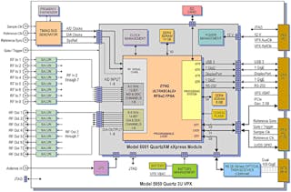
These Cots Sdr System Solutions Focus On 5g Electronic Design
![]()
Overview Of Wireless Pc Communication System Using Transceiver
![]()
Wireless Rf Module Rf Transmitter And Receiver Latest Applications
What Is The Difference Between Wifi And Cellular Connection Quora
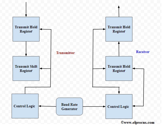
Basics Of Uart Explained Communication Protocol And Its Applications